Sequential Blinking!
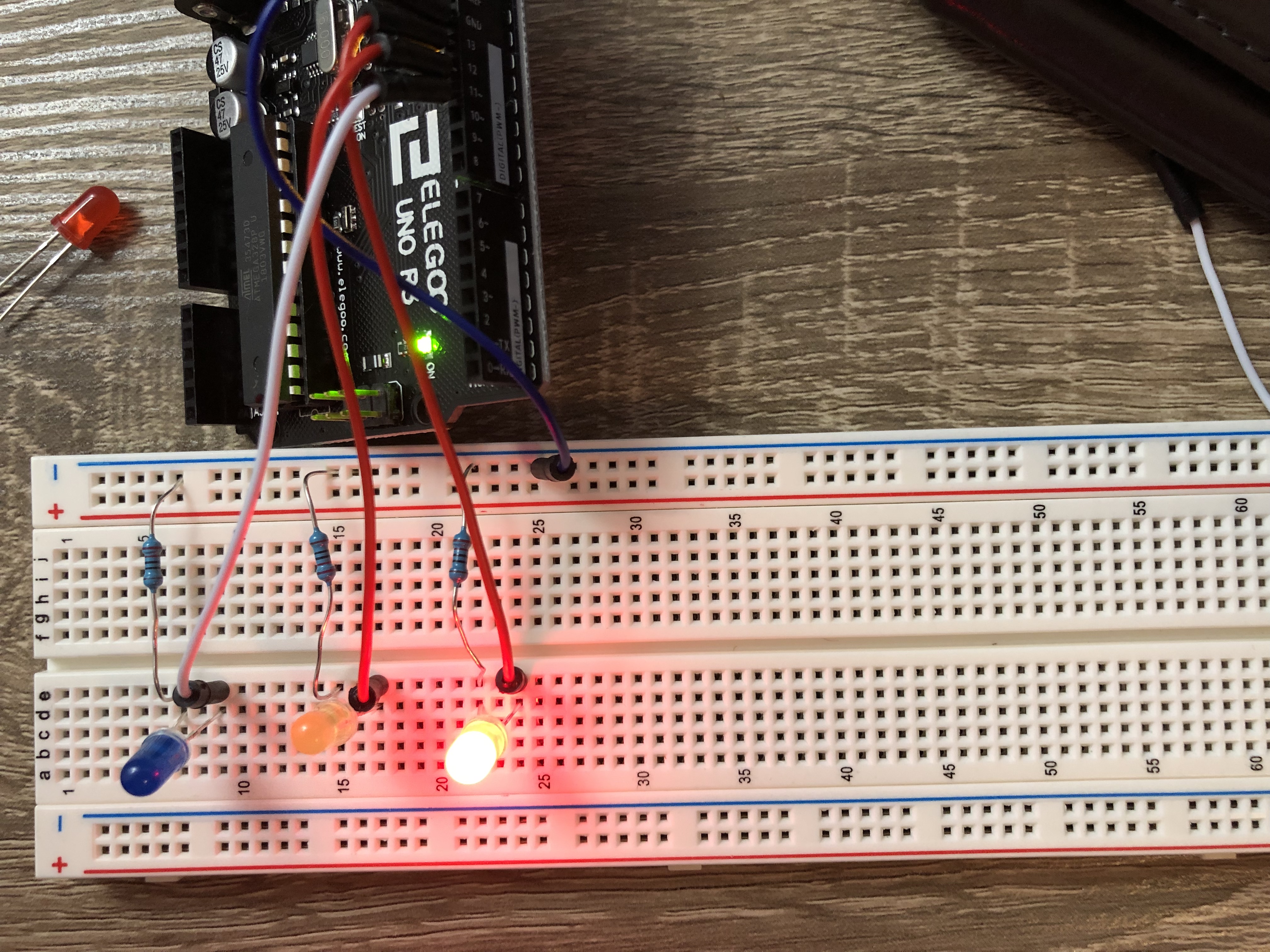
I built three separate circuits next to each other on my breadboard.
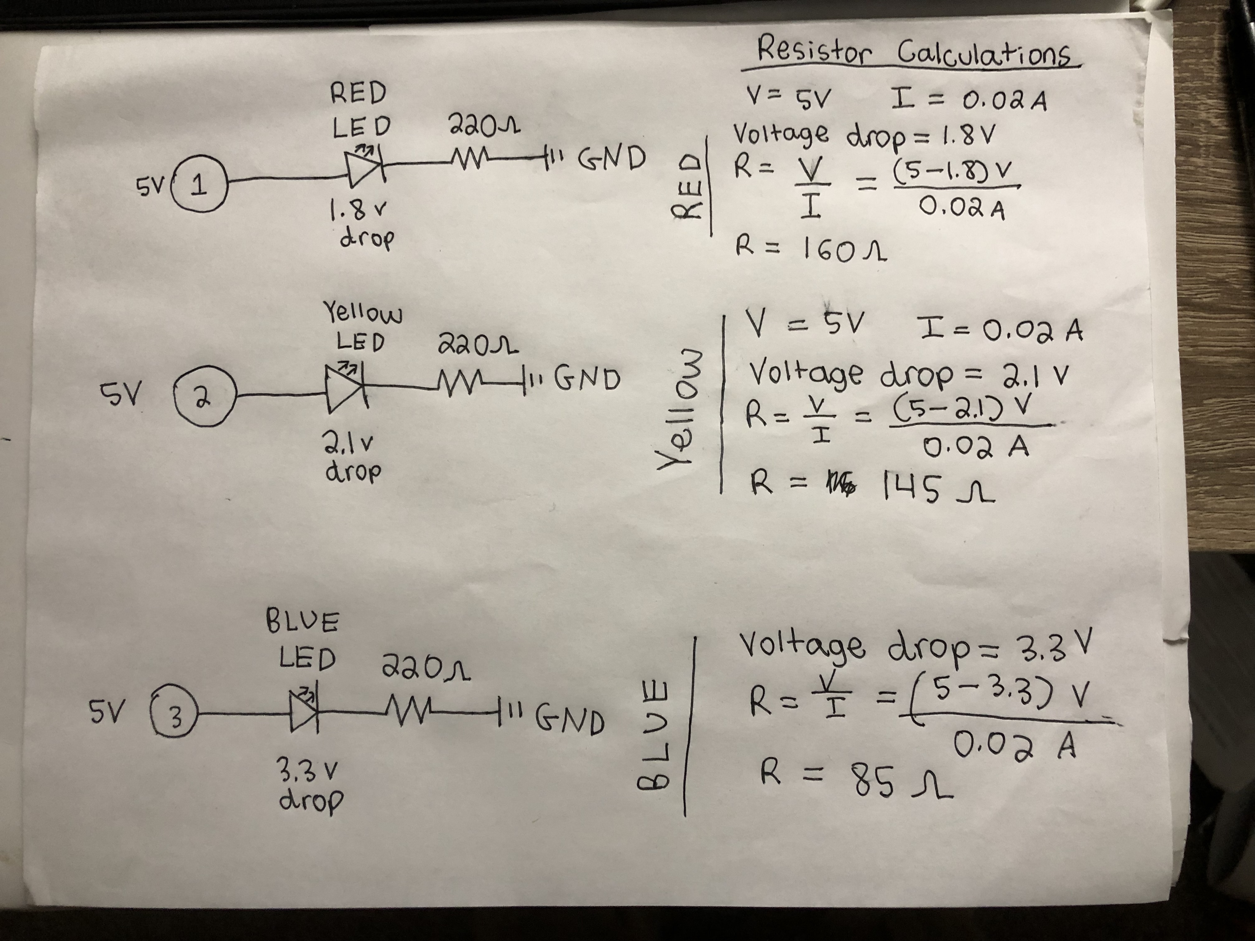
My schematics show 220 ohm resistors being used, as that value was above all the calculated resistances needed to create the optimal current of 0.02A.
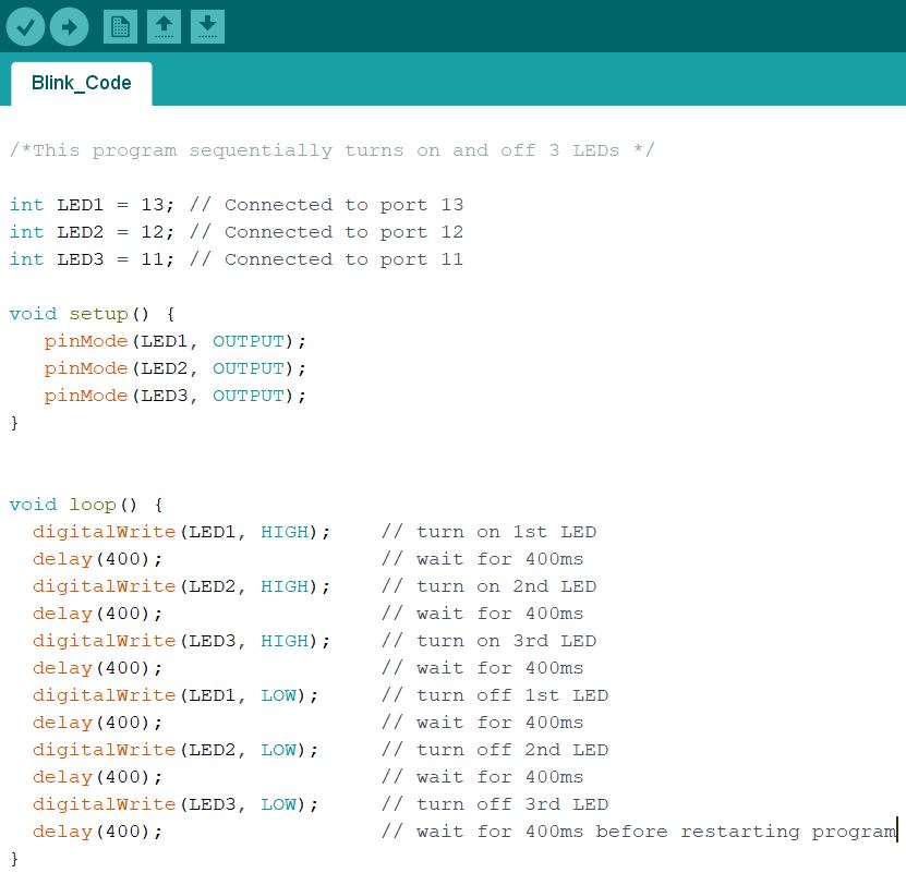
The loop portion of my program uses a 400 millisecond delay to turn on and off different LEDs.
This GIF shows my circuit's operation and light show in action!