Photoresistor Circuit!
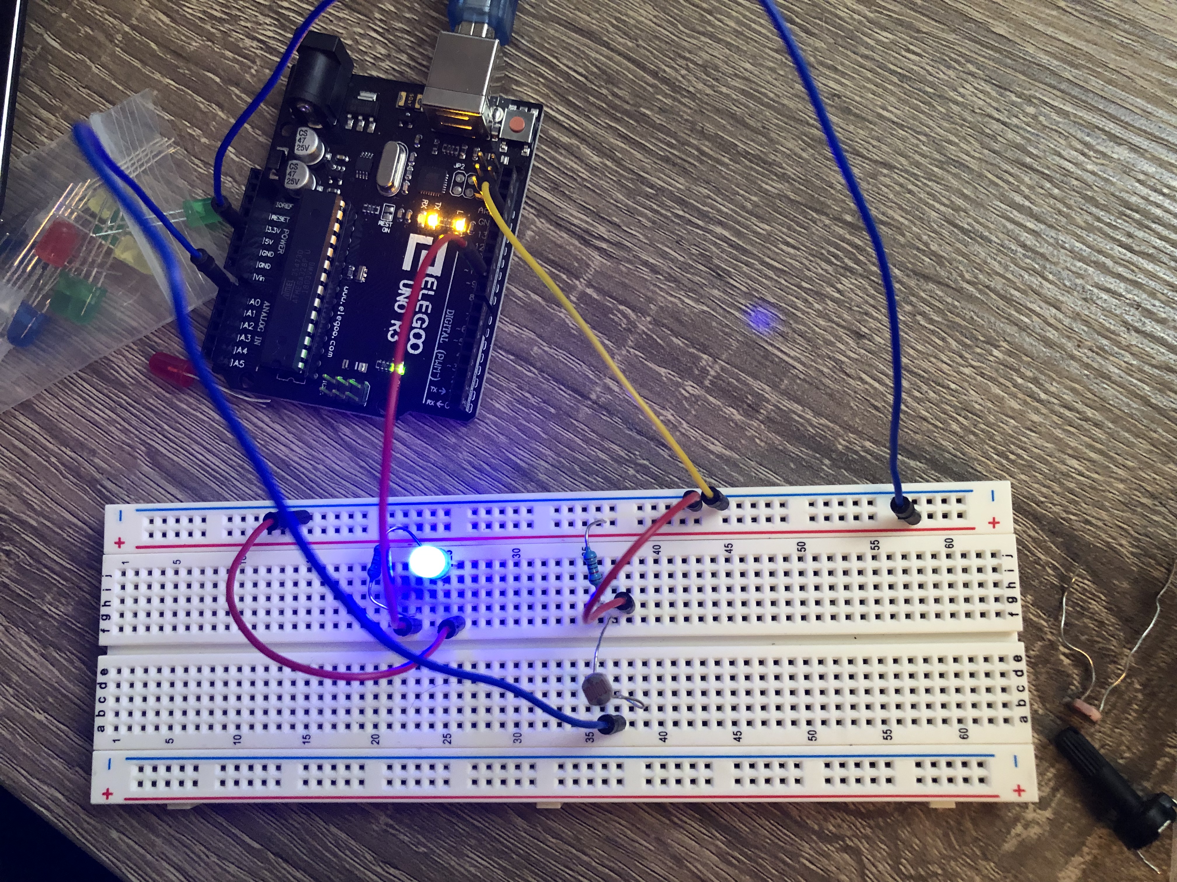
In my breadboard I used a 10k ohm resistor in combination with a 220 ohm resistor, to properly balance the load with my photoresistor.
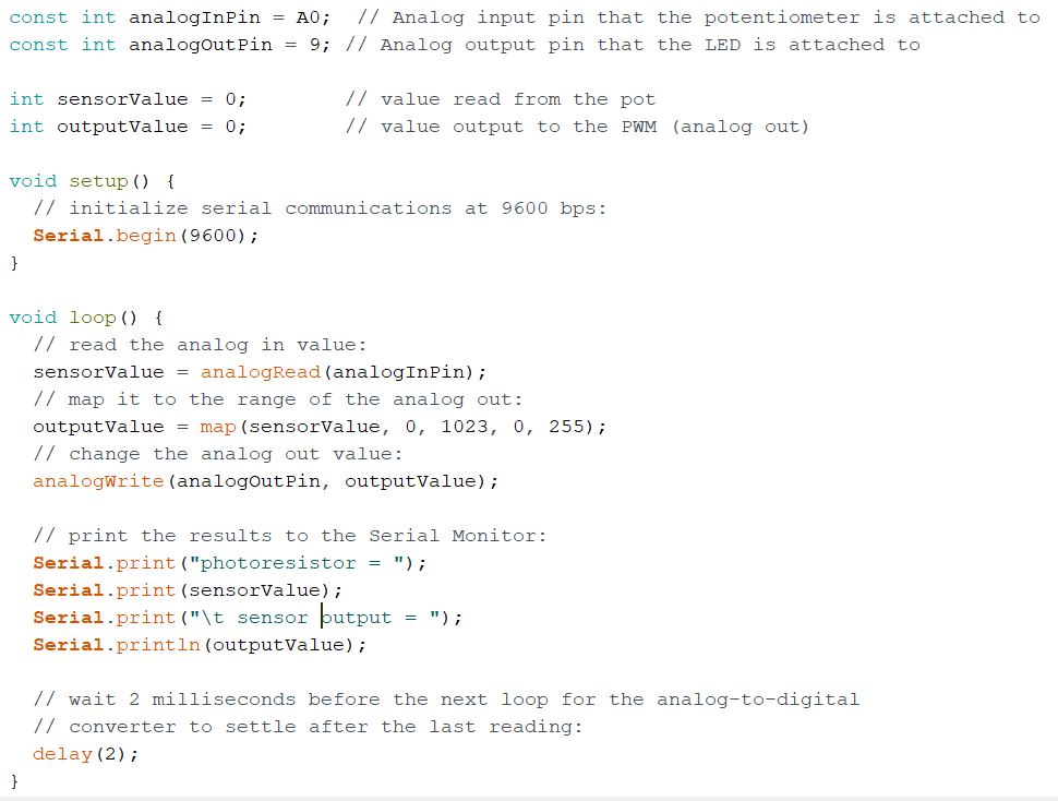
My program prints the photoresistor and sensor output values to the serial monitor.
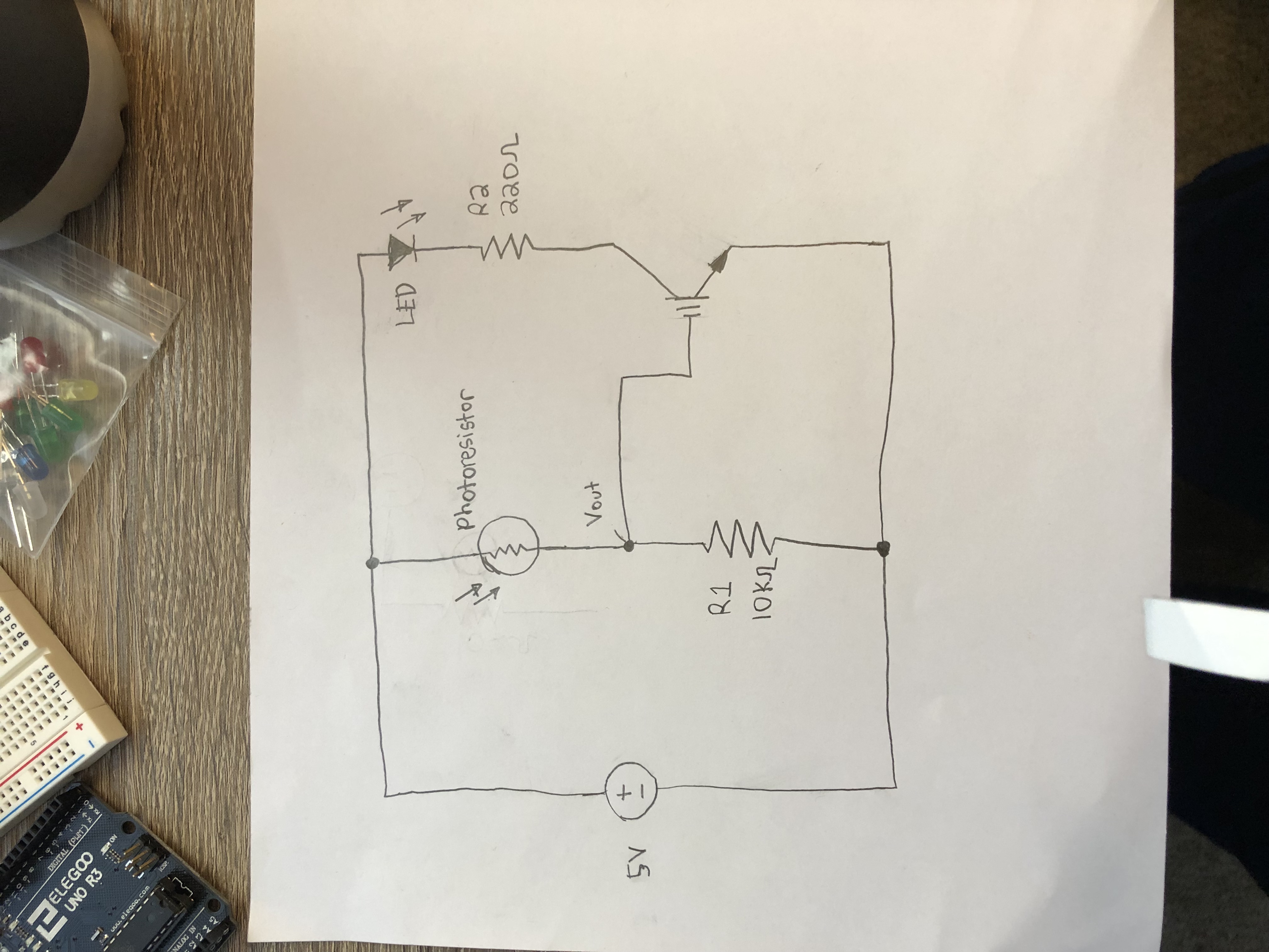
My schematic drawing of my circuit shows a 5V source connected to a voltage divider with 2 resistors, sensor, and LED.
This GIF shows how light affects my circuit. When I cover the photoresistor the light is affected!